 So, the concept is to harness the site forces to influence, or suggest a generative list of jumping-off points for design. Shown above is the site that I have spent this semester designing on. It is located in Baltimore, MD on the campus of the Maryland Institute College of Art, MICA for short. In beginning to take site inventory of the players and shakers that make this location unique, it should first be understood that in addition to merely documenting what is there, I feel this generative process should take into account the importance or historical significance of these found conditions.
For example, one of the most interesting characteristics on the site is the river that runs through it. You may say, 'so there's a river,' but it goes deeper. The Jones Falls River provided power for the steel mill industry of Baltimore, essentially acting as the generative source of the City itself; and this new design can interact with this amenity. Additional site forces which I'll simply list for brevity's sake include: North Ave, a three-lane, bidirectional East-West highway connecting Route 1 to West Baltimore, North Howard Street, which extends from Camden Yards through to Towson, light rail lines, the CSX freight rail line, bounding the site to the West, three existing buildings, service roads, existing vegetation, unique arching on the underside of the North Ave bridge, the Northwestern wind that influenced the layout of the old grid of Baltimore...and on top of this the 'ground' floor exists on two separate levels, the river basin, and the man-made City level 25 feet above it.
My initial thought process would be to overlay the site with a rectangular form that could be divided into strips. These strips would then be influenced by force lines which would themselves be dictated by these found conditions. On top of this, a value system would be enforced, giving hierarchical response in the shape to the more influential forces. Multiple iterations of this cause and effect system could be analyzed, perhaps incorporating a slide bar to visualize the deformations created when one, two, or more forces assume a dominant role, in relation to others that become subversive or passive in the dialogue.
The following diagram set portrays an example of what this could look like. This series is part of a tutorial on diagram story-boarding by Alex Hogrefe -
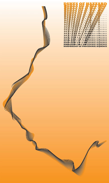
This set uses pedestrian movement patterns as a parameter for the iterative process. Different permutations of end conditions seem to be influenced by other forces on the site. The resulting form however seems to be generated as a byproduct of splitting a lofted geometry. In the first diagram(s), the splines are seemingly defined by the solids and voids found on the site. The resulting form reminds me of the process I had used in Project 2 when digitally diagramming the relationship between the General Lee and the camera's movement. The model represents a physical manifestation of the blend tool found in Adobe Illustrator.
The second set by Hogrefe further relays this observation -
Compared side to side to my Project 2 model -
I would like to take this process one step further. Rather than depicting the site forces with a series of static models, I would want to generate a manipulative surface that shares the same concept, but can be deformed by translating site forces or adjusting their influence through the Grasshopper derived digital model space. These deformations could then be visualized within the Rhino program, or exported as an animation, and when viewed simultaneously, may give rise to interstitial iterations that spark ideas for design form I am definitely open to other techniques to document the forces at work, but this is where my thought process has evolved for now.


